Air Monitoring
Effective use of LDO fired boiler flue gas in carbonation of process liquor at alkali leaching based Tummalapalle Mill
Oct 25 2019
Author: Vipin Kumar Sharma, P.Sriharsha, J.Dinesh Kannan, L.KoteswaraRao, Suman Sarkar & M.S.Rao on behalf of Uranium Corporation of India Ltd.
Carbon dioxide (CO2) is a major greenhouse gas (GHG), into the atmosphere, and there is strong evidence that the buildup of GHGs is the primary cause of the global warming that has occurred in recent decades. CO2 concentration in the atmosphere has risen about 43% since the beginning of the industrial revolution in the mid-eighteenth century—half of that since 1980.
Tummalapalle project is alkali leaching based low grade uranium ore mining and milling project of India. Leaching of ground ore (80% passing, 74 micron particles -200 mesh) takes place by addition of sodium carbonate and oxygen. Boiler House is one of the important sections of Tummalapalle Mill for generation of steam which is used in various sections ex; SDU precipitation, counter wash and sustaining cake wash temperature in leach filters, redissolution of SDU cake in CPL and for initialization of chemical reactions inside autoclave. Total three boilers of capacity 15MT each are present at Tummalapalle Mill out of which two are in line and one is in standby condition. Boilers are oil fired and maximum 863 kg/hr light diesel oil can be fueled for each burner. Air pre heater is installed for each boiler in which boiler exhaust flue gases are used for preheating of air for burning of boiler fuel. After preheating, flue gas is released out to atmosphere via stack. Several experiments were conducted for carbonation of liquor by flue gas and satisfactory results achieved on initial stage.
KEYWORDS: Flue Gas, Carbon dioxide, Boiler House, Tummalapalle Mill, Uranium Corporation of India Limited, Caustic Lye, Sodium Carbonate, Sodium Bicarbonate.
NOMENCLATURE: SSR – Sodium Sulfate Recovery Unit, CPCB – Central Pollution Control Board, MoEF – Ministry of Environment, Forest and Climate Change, LDO – Light Diesel Oil, DG – Diesel Generator, SDU – Sodium Diuranate, ID – Induced Draught, TSS - Total Suspended Solid, TDS - Total Dissolved Solid, CPL – Clarified Pregnant Liquor, OSHAS - Occupational Health & Safety Assessment Series, ISO - International Organization for Standardization, BDL – Below Detection Limit, DL – Detection Limit, APH – Air Pre Heater, IBR – Indian Boiler Regulation.
1. Alkali leaching process & chemical reactions: Sodium bicarbonate generation takes place as per exothermic reactions (1,2,3,4) inside pressurized autoclave which helps in completion of chemical reaction in presence of oxygen. For autoclave operations, low concentration NaHCO3 is sufficient and it benefits in product precipitation. Addition of NaOH is done before leaching in autoclave for maintaining sufficient value of TDS in circuit.
2UO2 + O22UO3 (1)
UO3+3Na2CO3+H2ONa4UO2(CO3)3+2NaOH (2)
NaOH+NaHCO3 Na2CO3+H2O (3)
2FeS2 + 7O2 + 8Na2CO3 + 6H2O2Fe(OH)2 +
4Na2SO4 + 8NaHCO3 (4)
2NaHCO3+ΔNa2CO3+H2O+CO2 (5)
Filtration of autoclave discharge takes place after alkali leaching for solid liquid separation. Filtrate goes to clarification unit for removal of remaining TSS. Precipitation of clarified liquor takes place for precipitating Sodium diuranate in presence of 48% conc. NaOH (reaction 6). SDU redissolution scheme is used for increasing U3O8 concentration in feed liquor to precipitation.
2Na4UO2(CO3)3+6NaOHNa2U2O7+6Na2CO3+3H2O (6)
Precipitate goes to SDU thickener for solid liquid separation. Causticization of SDU thickener overflow takes place after addition of lime inside slaker. After passing through press filter, filtrate goes to SSR unit for recovery of byproduct sodium sulphate. Filtrate after treatment in SSR unit contains sodium hydroxide which needs to be converted into desired leaching reagent (reaction 7). Sodium carbonate is generated by addition of CO2 in carbonation tanks.
2NaOH+CO2Na2CO3+H2O (7)
Na2CO3+CO2+H2O2NaHCO3 (8)
Figure 1. Liquor Carbonation Flowsheet of Tummalapalle Mill.
2. Objectives of liquor carbonation:
a).Conversion of caustic lye liquor to desired leaching reagents,
b).Neutralization of caustic lye before discharge to tailings pond,
c).Minimizing procurement of reagents from other sources,
d).Control over economical expenditures,
e).Maximizing recovery of end product (SDU),
f).Control over usage of process water in system.
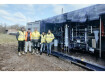
3. Carbonation Process at Tummalapalle Mill: SDU thickener overflow goes to carbonation circuit after processing at Causticization & SSR. Total four tanks of capacity 150 m3 each are available at Tummalapalle Mill for completion of carbonation (figure 2). pH of liquor is approximately 12.5-13.5 after receiving from SSR due to presence of caustic lye. Carbon dioxide addition takes place approximately 15-18 minutes into carbonation tanks after filling level approx. 75-80%. pH is monitored by online pH indicator situated inside every tanks (figure 1). CO2 feeding stops when pH reaches at 10.5-11.5. Caustic lye converts into sodium carbonate completely. Generation of sodium bicarbonate takes place in case of additional CO2 addition inside carbonation tanks. Maximum requirement of CO2 may reach upto 27 MT/day in Tummalapalle Mill. Presently, procurement of CO2 is done through purchase from other sources.
Figure 2. Four Carbonation tanks at Tummalapalle Mill.
4. Stack monitoring reports of Tummalapalle Mill: Stack monitoring of exhaust gases is a regular procedure to be followed by Tummalapalle Mill as per recommendation of CPCB/MoEF. It is done by Lab, approved by MoEF, OHSAS 18001 and ISO 9001. All values of carbon dioxide were under prescribed limit (table 1).
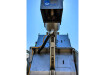
Figure 3. Schematic drawing of flue gas generation via APH and Chimney.
Table 1. Composition range of CO & CO2 gases at various sections of Tummalapalle Mill.
Figure 4. Cross sectional diagram of flue gas passing by Air Pre Heater (APH).
Table 2. Boiler (15 MT) stack parameters at Tummalapalle Mill.
[Test Method: IS11255(P 3)2008].
Table 3. Stack Volume details of CO2 gas for Boiler (15 MT)
at Tummalapalle Mill.
5. Online Experiment Setup at Tummalapalle Mill: Three Pass Wet back smoke tube boiler each of capacity 15 Tons/Hr at 17.5 Kg/cm2g design pressure has been envisaged for the supply of steam to process plants under IBR Design Code 1950 (figure 3). Each unit is provided with control of fuel and water. Boilers are PLC system operated. Engineering modifications done by installing blower fan at the outlet side of APH (figure 4) for feeding of flue gas for Batch & Continuous trials (figure 5).
Figure 5. Effective use of Boiler flue gas for carbonation of process liquor at Tummalapalle Mill.
6. Batch Experiment Trial 1 & Results: Trials were conducted at boiler house for carbonation of process liquor. Initial trials conducted by feeding flue gases inside 5 liter canes full of process liquor. Trials were done in 4 batch processes (figure 6) and satisfactory results observed after analysis in CR&D lab. (table 4), [graph 1(a),1(b)]
Figure 6. Carbonation trial in batch process.
Table 4. Chemical compositions of liquor in carbonation process (batch trial 1).
Graph 1 (a). Effect of flue gas in sodium carbonate (Na2CO3) concentration during liquor carbonation (batch trial 1).
Graph 1 (b). Effect of flue gas in caustic lye (NaOH) concentration during liquor carbonation (batch trial 1).
7. Continuous Experiment Trial 2 & Results: Process liquor was collected inside 200 liter tank. Boiler flue gas (average 203°C) was fed continuously 120 minutes inside tank and samples were collected at time interval of 30 minutes (figure 6). Continuous increase in sodium carbonate and decrease in caustic lye values were achieved and sufficient carbonation achieved (table 5), [graph 2(a),2(b)]. Trials still continues before final implementation in Uranium mineral processing plant.
Table 5. Chemical compositions of liquor in carbonation process (continuous trial 2).
Graph 2 (a). Effect of flue gas in sodium carbonate (Na2CO3) concentration during liquor carbonation (continuous trial 2).
Graph 2 (b). Effect of flue gas in caustic lye (NaOH) concentration during liquor carbonation (continuous trial 2).
8. Environmental benefits of flue gas usage:
Carbon dioxide (CO2), a trace gas, is the most important greenhouse gas in the atmosphere. Similar to other gases, the concentration of CO2 is measured in parts per million. In the past 400,000 years, the concentration of CO2 varied between 200 ppm to 280 ppm. Since the mid-19th century, the concentration of CO2 has been rising and reached 410 ppm in June 2018. In the late 1950s, the annual rate of increase of CO2 concentration was about 0.73 ppm per year, and from 2005-2014 the increase was about 2.11 ppm per year. Main effects of CO2 in atmosphere are as following;
a) Climate change,
b) Greenhouse effect,
c) Global warming,
d) Air, Soil and Water Pollution,
e) Human Health Impacts,
f) Ground-Level Ozone,
g) Acid Rain,
h) Ocean Acidification,
i) Carbon Fertilization.
Figure 7. Atmospheric CO2 concentration in parts per million by volume (ppm) at Mauna Loa, Hawaii (Keeling & Whorf 1997).
9. Conclusions: CO2 may cause severe health injury if crosses prescribed limits in atmosphere. Uranium Corporation of India Limited is a public sector unit, contributing towards neat and clean energy of nation in terms of nuclear fuel of country since more than 50 years. Experiments are being conducted for effective use of flue gases emitted from boiler house. It is possible for Tummalapalle Mill because carbonation of liquor is an important process of unit. Tests are still under progress for effect of carbonated liquor in operations. These modifications are small step towards neat & clean energy of Nation by UCIL under DAE.
ACKNOWLEDGMENT: We thank the management of Uranium Corporation of India Limited, Tummalapale Project. We also thank Shri C.K.Asnani, (C&MD), Shri S.R.Pranesh, D(T) & Dr. A.K.Sarangi, ED(P.N.) for their valuable suggestions towards improvement and CR&D activities at Tummalapalle Mill.
REFERENCES:
1. Brandon Reynolds, K. J. Reddy and Morris D. Argyle, “Field Application of Accelerated Mineral Carbonation”, Minerals 2014, 4, 191-207.
2. Udara S.P.R. Arachchige, Dinesh Kawan, Lars-André Tokheim, “Model Development for CO2 Capture in the Cement Industry”, International Journal of Modeling and Optimization”, Vol. 3, No. 6, December 2013.
3. Marco Mazzotti, “Mineral carbonation and industrial uses of carbon dioxide”, IPCC Special Report on Carbon dioxide Capture and Storage, Chapter 7.
4. Jung Hyun Kim and Woo Teck Kwon, “Semi-Dry Carbonation Process Using Fly Ash from Solid Refused Fuel Power Plant”, Sustainability 2019, 11, 908.
5. Willie Soon1, Sallie L., Baliunas, “Environmental effects of increased atmospheric carbon dioxide”, Clim Res, Vol. 13: 149–164, 1999, October 26.
6. Vipin Kumar Sharma and L. Rajesh, “Case study of air quality at Tummalapalle Mill and effective actions for improvement”, DAESOHPM 2019.
7. https://climate.nasa.gov/vital-signs/carbon-dioxide/


Events
Apr 22 2024 Hannover, Germany
Apr 23 2024 Kuala Lumpur, Malaysia
Apr 24 2024 Sao Paulo, Brasil
May 05 2024 Seville, Spain
May 13 2024 Munich, Germany